Flow Conditioner Use and Applications
History of Flow Conditioners & Straightening Vanes
Flow conditioners first began to be used in the 1940s, as it became more apparent from laboratory testing that the impact on the flow profile from piping located upstream of the DP meter had a significant impact on the accuracy of the installed meter. In the early 1900s, the testing facilities (principally Alden Research Laboratory, Holden, MA) had limited line size capabilities and space to model the actual field piping. This made it difficult for the discharge coefficient assigned to the calibrated meter to properly reflect the piping into which it would be installed.
Flow Conditioner Application & Design
The principal use of a flow conditioner is to improve the flow profile of whatever is being measured as it approaches the flow meter. One of the most important elements of designing a successful flow meter installation is consideration of what the upstream piping impact is on the flow profile; for example, we know from years of research that a 90-degree elbow produces a non-uniform velocity profile as flow exits the elbow. If there is not adequate space between the discharge of the elbow and the location of the flow meter, significant errors can result. By inserting a flow conditioner on the discharge side of the elbow, the conditioner “converts” the non-uniform profile into one that either does not impact the accuracy of the flow meter or lowers the impact on the meter.
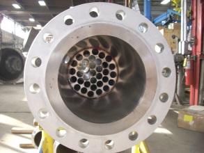
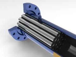
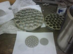
There are several flow straightener designs, such as the honeycomb, tubular bundle, and straightening vane, all of which are used for specific flow profile conditions. Flow conditions refer to the flow velocity profile and irregularities in it, such as swirling flows and other disturbances to the otherwise blunt velocity profile, which is ideally suited for accurate flow measurement. One important aspect of the selection and application of the straightening device is that there is adequate space between the discharge of the straightening device and the downstream meter. If the space is too short, exchanging one set of velocity profile conditions for another one may not achieve the desired results.
The flow conditioner material can be whatever is suited for the application conditions. Typically, carbon steel or stainless steel is most suitable.
PFS Flow Conditioners
PFS has completed over 2,500 independent laboratory flow calibrations on both water and gas meters, many of which replicate or model the actual field piping conditions into which the meter will be installed. The benefit of this dataset is that the decision to use a flow conditioner/straightener can be more effectively and wisely determined. It is also used to:
- Determine which type of conditioner will resolve the velocity profile situation
- Determine the increase in energy consumption that will occur
- Be sure that the overall system will operate properly
- Design the flow meter to improve its installed accuracy with the upstream conditioner in place
PFS Flow Conditioners are designed and manufactured to meet temperature and pressure requirements based on customer specifications. These can be manufactured in Carbon Steel and Stainless Steel, depending upon the service. They can be furnished in the Multi-Hole design or Tube Bundle design in virtually any size required. Other materials can be manufactured based on service requirements.