Innovations in Venturi Meter Design and Performance
History and Evolution of Venturi Meter Technology
SCOPE: The classical Venturi tube design and performance have been well documented over more than 100 years of its use as a reliably accurate flow measurement primary. The code of construction and performance for the classical type meter has been well defined by a number of scientific bodies over the years; codes such as the ASME –MFC3M and ISO 5167 were developed to imply that if a Venturi meter were constructed according to the strict requirements of the code, the performance of the Venturi meter, relative to accuracy, repeatability, installation requirements and other operational aspects would be as stated in the code(s). Conversely, with very few exceptions, the manufacturer could not change any aspect of the meter design, interior finish, length or tolerance and still use 1 of 3 standard discharge coefficients that most codes claimed were the result of the specified manufacturing process.
The codes specified the minimum and maximum line size that was applicable, the overall length of the meter, the location of the pressure taps, the configuration of key sections within the body of the meter and the piping configuration into which the meter could be installed to achieve the stated performance. Ergo, any change from the code requirements would invalidate the use of the meter according to what the code claimed was its performance. For instance, over the years, various manufacturers have built “insert style classical Venturi meters” which are not covered in any of the classical codes. Generally, they were developed and offered for a good reason such as shorter length, lower cost, and easier installation – however, their use and all of the operational claims of the code cannot be used because an insert-type classical Venturi meter, at least according to ASME-MFC3M and ISO 5167 does not exist.
With the introduction of the modified short form Venturi meter code, changes could be made to the physical configuration of the Venturi meter and further modifications could be developed, tested and proven to be valuable in terms of required space, cost and performance. The UVT (as was its patented name) eliminated a number of features that were disadvantageous such as “annular pressure chambers” and excessively long component sections thus improving the life expectancy of the meter, lowering its cost and headloss yet improving its basic accuracy – these improvements and many more since the mid-1960’s are the result of what can be described as the natural evolution/improvement of a product over time through careful design and testing processes.
Philosophical Difference Between the ASME/ISO Classical Codes and the Modified Short Form Code:
Clearly, the ASME and ISO codes governing the classical Venturi meter are what can be called “reactive” codes whereby the builder of the meter can reasonably expect the performance claims of these codes as belonging to every meter that is built according to the strict requirements of the code. There is no scientific progress in play with a reactive code – only the assumed assurance that each part built according to the code will perform in the same fashion and, rather than modify the meter to suit application conditions, budgets and size requirements, the user of the meter can never expect anything better than what the code allows.
The Modified Short Form Code (MSFC) is an “interactive” code which is to say that the designer/builder is free to make modifications to the basic design of the meter as long as appropriate testing and documentation is provided to support all claims. Interactive codes foster performance evolution because they provide a basic structure and design from which creative minds can contemplate and consider changes/modifications for a particular advantage. Once an appropriate range of independent testing is completed, the new design becomes fully documented and all of its benefits and features are available to the end user.
Understanding the Modified Short Form Venturi Meter
The intent of the Halmi MSFC is to provide a process whereby the accuracy, repeatability and headloss performance of a next-generation Venturi meter can be determined and proven. The exact geometry of the Venturi meter is the creation of its inventor and, it must be assumed, is based on either a requirement or desire for improved performance over those devices currently on the market. Such important details as internal geometry, angular intersections, length of key sections, location of pressure taps, interior surface condition and manufacturing tolerances are the responsibility of the inventor. Once the hydraulic shape of the Venturi meter has been defined, it must be thoroughly tested to determine its:
- Discharge coefficient value.
- Shape of the coefficient as defined by its relationship to pipe Reynolds number.
- Installation sensitivity based on testing “typical” disturbers for both upstream and downstream conditions.
- Tap location sensitivity.
- Headless across the profile.
- Accuracy and repeatability.
- Applicability for liquids, gasses, slurries, sludge, mixed media and varying viscosities must be determined and proven.
All testing shall be based on a two-sigma process and the collected data must be analyzed by a properly developed algebraic process. The proof of performance testing must take place in at least 3 physically independent testing facilities and as large a range of line sizes and throat sizes (beta ratios) as the independent testing facilities are capable of providing must be utilized and the data presented. The basis of acceptance of the performance claims must include firm documentation that the:
- Discharge coefficient is independent of both line size and throat size (beta ratio).
- Minimum pipe RD for constant discharge coefficient is determined.
- That the installation effects of various disturbers (elbow, tee, increaser, reducer, multiple elbows, valves, pumps, etc) are presented for both the upstream expected requirement for straight pipe as well as proof that there is no downstream straight pipe requirement as is the case for the UVT, NTV and HVT designs.
Evolution of the Use of the Halmi Modified Short Form Code (MSFC)
FIRST EXAMPLE:
The first example of the application of the Halmi-MSFC was the Universal Venturi Tube (UVT) as developed by Dezsoe Halmi during the mid to late 1960s. The inventor, Halmi, secured a US Patent (3,686,946) in June 1970. The following are key elements of the patent:
Object Of the Invention:
(patent article 30) “The object of this invention is to reduce the adverse effects on discharge coefficient of all types of flow pattern abnormalities without resorting to the expensive measures which characterize the classical Venturi tube”.
How does it achieve this performance?
(patent article 35) “The invention provides a new differential producer having an internal wall shaped to control the velocity distribution in the flowing stream by causing the fluid to form at least one vena contracta, with subsequent expansion and reattachment to the tube wall, between the inlet and throat pressure sensing taps.”
What was the benefit of the vena contracta?
(patent article 45) “The vena contractas tend to normalize the velocity distribution in the fluid stream passing the pressure-sensing taps, and thus make the metering device less sensitive to flow pattern changes and/or abnormalities in the entering stream”.
Additional benefits:
- (patent article 60-65) “It (the UVT) is as insensitive to the asymmetrical flow pattern defects as the classical Venturi tube, but does not require annular pressure-sensing taps.”;
- “With regard to head losses, length and cost, it is comparable to the flow tube.”;
- Pulsations in the pressures sensed by the taps are minimized”;
- The degree of flow pattern control can be changed easily”;
- “It can be used in the same range of line sizes as the classical Venturi tube”;
- “It has the same adiabatic expansion factor Y as the classical Venturi tube”;
- “It is less sensitive to manufacturing tolerances than any known tube”;
- “It provides a higher degree of uncalibrated accuracy than any known tube.”
Conclusions:
“In short, since the preferred embodiment performs better than the classical Venturi tube, and affords the same cost and length advantages as the flow tube, it may be considered a truly universal differential producer.”
Investigation, testing and performance of the UVT:
In the 1973 ASME Paper No. 73-WA/FM-3, the inventor describes in great detail the process whereby the concept of the UVT was imagined and for what purpose. The paper further describes in detail the wide range of tests that were used to prove and document the performance claims of the device. The format, content and step-by-step procedures as outlined in the paper have become the guiding principle for performing an exhaustive analysis of any proposed device. In short, if one follows the process steps outlined in the paper, the results can be considered accurate in terms of stating the performance of the device.
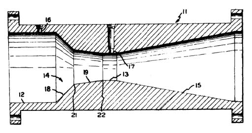
DRAWING FROM PATENT OF UVT
SECOND EXAMPLE:
From the mid-1970s to mid-1983, Halmi continued to refine his thinking, and evaluate significant performance documents for the UVT, the Classical and other differential producers in his continuing effort to improve on his UVT design. This thought process is another example of the interactive nature of the Halmi-MSFC and resulted in the next generation of the modified short-form product. In May of 1985, he was awarded US Patent# 4,516,434 for what was to become his “Nozzle Tube Venturi-NTV”. The following excerpt from the 434 patent describes his thought process:
“The instant invention relates to flow metering devices of the pressure differential producing type and more particularly to a Venturi-type flow metering device which is operative with minimum fluid energy losses.”
The use of Venturi-type flow metering devices is extremely well known, and a wide variety of such devices have heretofore been available. The classical Venturi tube is exemplary of one such device and comprises an elongated tubular member having a substantially straight inlet section, an elongated converging section of gradually reducing cross-section, a substantially straight throat section, an elongated downstream diverging section of gradually increasing cross-section and inlet and throat pressure sensing taps for sensing the static pressures in the inlet and throat sections, respectively. By applying the differential pressure between the inlet and throat taps in a flow equation, the rate of flow of a fluid through the device can be determined. Classical Venturi tubes of this type have proven to be effective for metering the flow rates of both liquids and gasses. Further, classical Venturi tubes can be effectively used for metering the flow rate of fluids containing suspended or entrained solids since they do not easily become fouled and, in fact, exhibit somewhat of a self-scouring effect. However, while classical Venturi tubes have proven to be effective for metering fluid flow rates, they have been characterized by relatively long laying lengths, and, therefore, they have generally been relatively expensive to manufacture compared to other known flow metering devices.
In addition to the Classical Venturi tube, a device known as the Venturi nozzle is also widely used in flow metering applications. A Venturi nozzle has a substantially straight inlet section, an elliptical converging section of reduced length, and a substantially straight throat section. A Venturi nozzle can be constructed with a substantially shorter laying length than a comparable classical Venturi tube. However, in a Venturi nozzle, the inlet end of the converging section extends substantially perpendicularly inwardly from the inlet section and then extends arcuately in a downstream direction. The inlet end of the converging section of the Venturi nozzle therefore acts somewhat like a dam that tends to trap solids that are suspended or entrained in the fluid passing through. Hence, the Venturi nozzle does not have the self-scouring effect found with classical Venturi tubes.
Another flow metering device of the differential producing type is commonly known as the universal Venturi tube and is disclosed in U.S. patent to Halmi No. 3,686,946. The universal Venturi tube comprises a substantially straight inlet section, an inlet cone that extends inwardly in converging relation from the inlet section, a throat cone that extends in converging relation from the inlet cone at a reduced angle relative to the inlet section, and a substantially straight throat section. Pressure sensing taps are also provided in the inlet and throat sections of a universal Venturi tube for sensing the static pressures in these areas. The intersections between the inlet and throat cones and between the throat cone and the throat section are preferably both of substantially sharp configurations so that preferably at least two vena contractas are formed in a fluid passing through the device. The universal Venturi tube has a self-scouring effect similar to the classical Venturi tube, it can be constructed with a reduced laying length, and it is operative for providing accurate flow measurements. However, the energy losses in a fluid passing through the converging section of a universal Venturi tube are substantially greater than the energy losses in fluids passing through the converging sections of comparable Venturi tubes or Venturi nozzles,” (the above was excerpted from the 434 patent directly).
Object of the Invention: NVT
Careful penetration of the above provides a clear definition to the manner and method Halmi was developing in his thought processes to gain better performance than was provided by the UVT. The following is excerpted from the 434 patent:
“The instant invention (NVT) provides a novel flow metering device of the Venturi type which has advantages over all of the above-mentioned devices. The device of the instant invention can be constructed in a reduced laying length, it has a self-scouring effect, it has minimum energy losses, it provides accurate flow measurements, and it can be constructed with reduced manufacturing costs.”
How does it achieve this performance?
“The device of instant invention comprises a shaped tubular member comprising a substantially longitudinally extending inlet section, a converging section which extends in converging relation from the inlet section, a substantially longitudinally extending throat section, and preferably also a downstream diverging section. The converging section comprises an inlet cone portion that extends angularly inwardly relative to the inlet section and a throat cone portion that extends angularly inwardly from the inlet cone portion to the throat section, the inlet cone portion, however, being at a reduced angle relative to the inlet section. An important feature in the device of the instant invention that distinguishes it from the devices of the prior art, in particular the universal Venturi tube, is the provision of rounded intersections between the inlet cone and throat cone portions and between the throat cone portion and the throat section.”
What was the benefit of this design?
“These rounded intersections are provided to prevent the formation of vena contractas in a fluid passing through the device so that energy losses in the fluid are minimized. As a result of the rounded intersections in these areas, the energy losses experienced in the device of the instant invention are substantially less than those realized with the universal Venturi tube. The device of the instant invention has a self-scouring effect similar to that found in a universal Venturi tube, it can be construction in a reduced laying length, and it is operative for providing accurate flow measurements.”
Additional benefits:
“The device of the instant invention can be manufactured economically because of its reduced laying length, and further reductions in manufacturing costs can be realized as a result of the rounded intersections hereinabove described, rounded intersections being substantially easier to form in machining operations than the sharp intersections provided in the known devices of this kind. Accordingly, the device of the instant Venturi is economical to manufacture, and it is operative with minimum energy losses.”
Conclusions:
With his invention of the UVT, Halmi established both the theory and the proving process that is the essence of the Halmi-MSFC code. By analyzing each portion of the classical Venturi meter and developing an understanding of what would be beneficial to the user, the UVT was born. Using this same process, he further refined his thinking with the development of the NTV. The Halmi-MSFC code is a performance code rather than a manufacturing code as is the case with the ASME MFC-3M and ISO 5167. Because the Venturi meter performance demanded by the Halmi code is significantly greater than that required by either the ASME MFC-3M or ISO5167, its benefits are higher accuracy, lower energy consumption, greater design flexibility in terms of modifying the standard product to suit specific application conditions or requirements, lower cost and shorter laying length.
THIRD EXAMPLE:
By the time Halmi completed the NTV development and testing and introduced the product to the market, he was already contemplating a new version of the technology. Since the mid-1970s available testing laboratories have dramatically expanded their line size, pressure and flow rate range capabilities. Competitive flow measurement technologies had been developed and introduced to the market such as magnetic and ultrasonic and one of their main claims of superiority was that they were “full port” devices so their headloss was non-existent. Careful analysis of the application of these electronic devices results in a different picture. Because both of these technologies have a low-velocity limit, which in most cases is substantially higher than the minimum flow rate that a Venturi can operate within, they often needed to be installed in a reduced pipe section which had inefficient reducers on both ends in order to elevate the minimum flow rate velocity thus obtain the claimed accuracy.
Object of the Invention:
By 1986, Halmi had again developed a third-generation modified short form Venturi which he called the Halmi Venturi Tube (HVT). The main objective of this invention was to provide all of the benefits of the prior generations but with still lower energy consumption/headloss. As it turned out and based on the extensive testing that he performed, the HVT had additional and significant benefits over any known flow meter.
How does it achieve this enhanced performance?
The HVT inlet section was substantially changed to a single 30-degree angle with a blended transition into the cylindrical throat section. Eliminating the dual angle of the NTV and UVT resulted in approximately 20% lower energy consumption/headloss depending on the beta ratio (d/D) of the meter.
Additional benefits:
Because Halmi applied the same rigorous testing process to the development of the HVT, additional performance benefits were uncovered:
- The minimum pipe Reynolds number that the HVT could operate at is the lowest of any true Venturi meter ever developed. His prior devices had a bias error shift on the meter’s discharge coefficient at +/- 80,000 pipe RD where the HVT exhibited no coefficient bias down to +/-75,000 pipe Rd which means that the HVT can operate at standard accuracy at a lower flow rate than any other true Venturi meter can.
- As was the case with the UVT and, to a lesser degree with the NTV products, the differential noise created by the dual inlet angle design caused what was termed “noisy” readings that resulted in an apparent erratic operation of the DP transmitter and unstable indicated flow rates at certain differential pressure levels.
- As noted above, it also had an approximate 20% lower energy consumption/headloss.
Conclusions:
There are significant benefits when using a Venturi meter for accurate, repeatable and long-term reliability as compared to any other type of flow meter. With the extremely large installed base of the modified short-form type meter in a wide range of application conditions, the opportunity to improve the quality and performance of your measurement process is virtually unlimited.
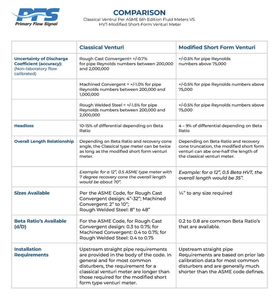
DIRECT COMPARISON OF THE HVT AND THE ISO 5167 VENTURI FOLLOWS ON THE SPREADSHEET BELOW.